Described here is a synthesised VHF Airband receiver with good performance at reasonable cost. The receiver covers 110 MHz to 136 Mhz.
The circuit comprises of a double conversion superhet with IF's of 10.7 MHz and 455 kHz. High side mixer injection is used to avoid strong FM broadcast image frequencies. The local oscillator uses a VCO controlled by a dedicated VHF synthesiser IC (TDA154170) which is in turn controlled by a PIC processor. Channel spacing is 8.333 kHz as this has been the global standard for some years now.
The front end consists of a voltage controlled tunable bandpass filter followed by a RF amplifier. A level 7 diode DBM is used for the first mixer to enhance strong signal performance. The IF amplifier consists of a transistor and dedicated AM receiver IC (TDA1072). IF passband filtering is achieved using a 10.7 MHz crystal filter and a 455 kHz ceramic filter. The second conversion takes place in the TDA1072 using a separate 10.245 Mhz crystal oscillator.
AGC is applied to the RF amplifier from the TDA1072 and internally to the chip. Receiver sensitivity is good, useable down to -120dBm @ 80% modulation depth. Selectivity is determined by FL1 and FL101.
Squelch control is provided by a op amp monitoring the AGC rail, it is important to use a rail to rail op amp in this position. The rest of the quad op amp is used for buffering and audio pre-amplification. Audio is raised to speaker level by a LM381 power amp.
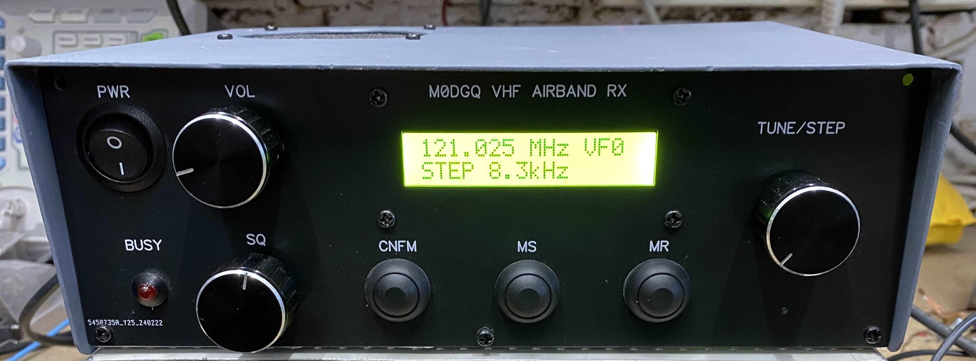
The synthesiser IC provides VCO and RF bandpass filter tuning voltage which track across the 110 -136 MHz band. The PIC16F628A sends a sixteen bit serial frequency data word to the synth IC and display data to the 16 X 2 line LCD. Five channel memories are provided, more could be added by tinkering with the code. Tuning steps of 8.333 kHz, 100 kHz and 1 MHz are selectable, incremented or decremented by the rotary encoder.
The front end RF coils are wound on 5mm formers with VHF core using 18swg wire, i salvaged the formers and screening cans from a scrap Pye Westminster pmr set. All other coils were wound on 10EK AND 10EZ type formers, the larger core type is used for L101 these formers are readily available from Aliexpress etc.
The code for the PIC is written in assembly and was compiled using mplab. Both asm and hex files are listed here, it is important that when programing the PIC you load start up frequency and display data into eprom for the first six address's starting at h00 ending h05 for frequency word and h40 to h45 for display data. The data is listed in the code and a screen shot of the initial eprom contents is shown.
The schematic is spread over several sheets and should be easy to follow. When winding the VCO coil it is recommended to cover the coil with Q-dope or varnish to avoid microphony. The receiver uses two PCB's, one for the RF section and one for the VCO controller. This was done as the controller is used in other projects.
Here is a youtube link to the set in use. DEMO
Barry Zarucki M0DGQ
HOME